As lithium-ion battery technology continues to evolve, lithium polymer (LiPo) batteries have become the cornerstone of modern electronic devices. From smartphones and tablets to wearable technology and IoT devices, proper battery selection is crucial for device performance, safety, and longevity. This comprehensive guide provides engineering professionals with essential knowledge for selecting, implementing, and optimizing lithium polymer batteries in electronic design applications.
Understanding Lithium Polymer Battery Technology
Core Concept and Architecture
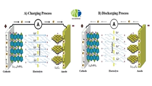
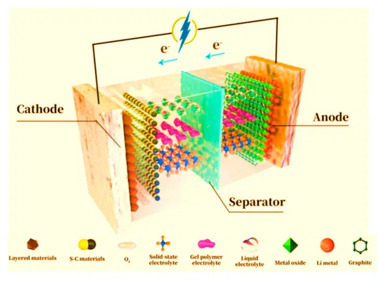
Lithium polymer batteries, also known as high-molecular lithium batteries, represent a significant advancement in rechargeable battery technology. The fundamental distinction between LiPo batteries and traditional liquid electrolyte lithium-ion cells lies in the electrolyte composition. Instead of liquid electrolyte solutions, polymer batteries utilize a gel-based polymer electrolyte matrix, which provides enhanced stability and safety characteristics.
This polymer electrolyte system consists of a solid or quasi-solid polymer membrane that facilitates lithium-ion transport between the anode and cathode during charge and discharge cycles. The polymer matrix typically incorporates lithium salts dissolved in organic solvents, creating a conductive medium that maintains ionic conductivity while providing mechanical stability.
Technical Advantages and Performance Characteristics
Lithium polymer batteries exhibit several key performance advantages that make them particularly suitable for modern electronic applications:
- High Energy Density: LiPo batteries deliver exceptional energy density ratios, typically ranging from 150-250 Wh/kg, enabling extended device operation times within compact form factors.
- Extended Cycle Life: Advanced polymer electrolyte formulations support 500-1000+ charge-discharge cycles while maintaining 80% capacity retention, significantly reducing total cost of ownership.
- Enhanced Safety Profile: The solid polymer electrolyte eliminates electrolyte leakage risks and reduces thermal runaway probability compared to liquid electrolyte systems.
- Customizable Form Factors: Manufacturers can produce batteries in virtually any shape or size configuration, optimizing space utilization in electronic device enclosures.
- Lightweight Construction: Aluminum-plastic laminated packaging reduces overall battery weight while maintaining structural integrity and thermal management capabilities.
- Low Self-discharge Rate: Polymer batteries typically exhibit self-discharge rates below 3-5% per month, enabling extended shelf life and standby operation.
Voltage and Capacity Specifications
Nominal Voltage Characteristics
Lithium polymer batteries operate with a nominal voltage of 3.7V, which represents the average voltage during normal discharge conditions. The complete voltage operating range spans from 4.2V (fully charged) to 3.0V (discharge cutoff), with the following critical voltage thresholds:
Voltage Operating Parameters:
- Maximum Charge Voltage: 4.2V ± 0.05V (constant voltage charging phase)
- Nominal Operating Voltage: 3.7V (standard discharge reference)
- Minimum Operating Voltage: 3.0V (discharge protection threshold)
- Storage Voltage: 3.8-3.9V (optimal long-term storage conditions)
It’s crucial to understand that the capacity specifications listed in battery datasheets typically reference the total energy available during discharge from 4.2V to 3.0V. However, practical applications should implement discharge protection circuits that prevent operation below 3.2V to ensure battery longevity and prevent irreversible capacity degradation.
Capacity Calculation Methodology
Accurate capacity calculation requires comprehensive analysis of device power consumption patterns across multiple operational scenarios. The methodology involves evaluating both standby and active power requirements:
Capacity Calculation Formula:
Total Capacity = Max(Standby_Capacity, Operating_Capacity) × Derating_Factor
Where:
- Standby_Capacity = (I_standby + I_self_discharge) × Standby_Time
- Operating_Capacity = Daily_Power_Consumption × Operating_Period
- Derating_Factor = 1.2-1.5 (accounts for capacity degradation over lifespan)
Critical considerations for capacity calculations include:
- Self-discharge Current: Typically 3-10µA for quality LiPo batteries, must be added to device standby current
- Capacity Degradation: Plan for 20-30% capacity reduction over 2-3 year product lifecycle
- Temperature Effects: Capacity reduces by 0.5-1% per °C below 20°C operating temperature
- Discharge Rate Impact: High discharge rates (>1C) can reduce available capacity by 10-15%
Similar Posts